INSTALLATION, OPERATION & MAINTENANCE MANUAL
PLASMA BAR SERIES
MODELS: PB-18, PB-24, PB-30, PB-36, PB-42, PB-48, PB-54, PB-60, PB-66, PB-72, PB-78, PB-84, PB-90, PB-96
INTRODUCTION
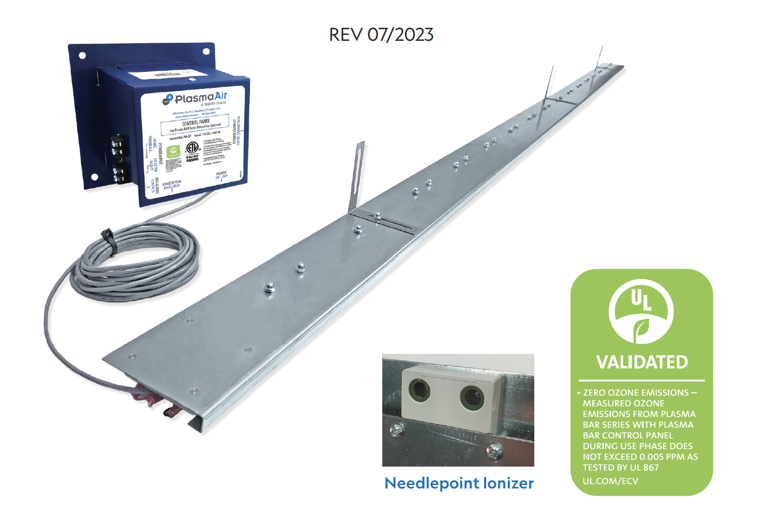
The Plasma BAR is a commercial quality, remote mounted needle point ion generator intended for installation in air handling units (AHU) and rooftop units (RTU). The Plasma BAR was designed to be mounted on the entering air side of a cooling coil inside of an AHU or RTU. The Plasma BAR is available in lengths of 18 inches up to 96 inches in 6 inch increments to suit a wide variety of AHU or RTU size applications.
This ionization equipment is effective in reducing harmful pollutants and odors and airborne pathogens (viruses, bacteria, and mold spores) by introducing positive and negative ions into the system airflow which is then delivered to the space. The length and quantity of the Plasma BAR ionization units are dependent on the internal cross sectional dimensions of the applicable AHU or RTU coil and the severity of the indoor air pollutants. The Plasma BAR ionization assembly is powered and monitored with a remote Plasma BAR Control Panel. One control panel can power up to two (2) Plasma BARs.
The Plasma BAR utilizes a feedback functionality that provides an electronic signal only when the ionizers are operating properly, i.e. when the ionizer is creating ions. The products use this signal to power an LED and initiate a relay that closes dry contacts.
MECHANICAL INSTALLATION INSTRUCTIONS
GENERAL MOUNTING CRITERIA:
CAUTION: The Plasma BAR product should not be installed downstream of a humidifier or exposed to any source of moisture.
CAUTION: This product is intended for mounting into metallic construction only. Installation must be such that the structural integrity or function of any heat transfer coil is not compromised. Do not fasten the Plasma BAR directly onto the fins or tubes of a coil.
- Mount control panel to allow access to the ionization unit power switch and connections. This product shall not be installed behind an inaccessible suspended floor/ceiling or a structural wall, ceiling, or floor. A minimum of 3/4" of clearance from metal surfaces for the ionization needles is recommended to prevent shorting.
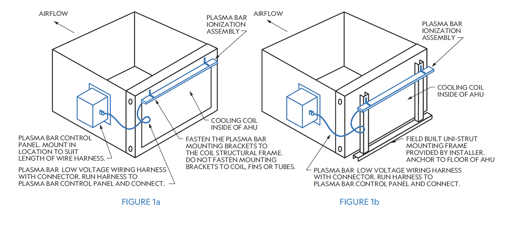
- The preferred mounting location for the Plasma BAR is on the entering face of the cooling coil inside of an Air Handling Unit (see Figure 1a). The mounting brackets provided shall be secured to the structural frame of the coil without damaging the coil's fins or tubes. Vertical uni-strut provided by the installer may be utilized to aid in mounting of the Plasma BAR if necessary. (See Figure 1b). The BAR can also be mounted downstream of the cooling coil as long as moisture carryover on the BAR is avoided.
- Once the Plasma BAR is securely fastened inside the Air Handling Unit, mount the Plasma BAR Control Panel at a nearby location to allow connection of the Plasma BAR wiring harness to the control panel (Figure 1a or Figure 1b).
- Connect the power to the control panel in the correct location and turn the switch to the "ON" position. (See Electrical Installation section of this IOM).
- Install Plasma BAR such that ionization needles are pointed down toward the floor of the AHU.
- Do not mount the BAR before the system filter.
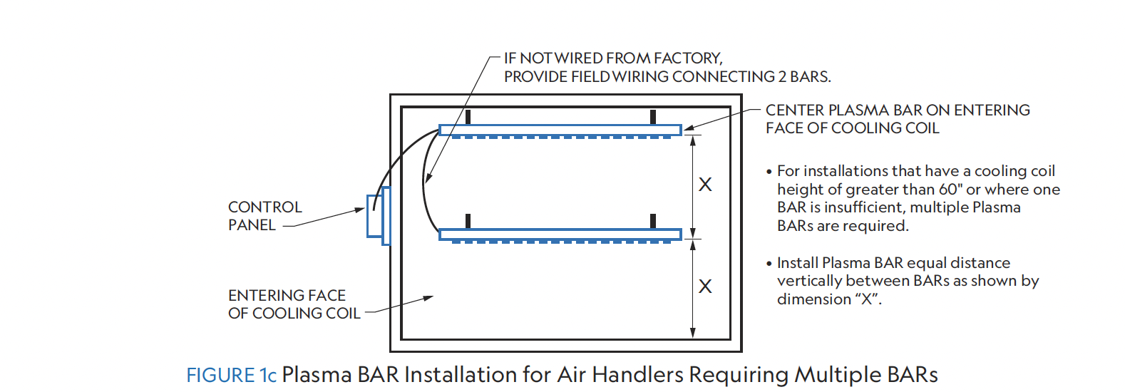
NOTE: If using multiple BARs on the same Air Handler, we recommend selecting two BARs of equivalent length in order to mitigate the possibility of ion agglomeration. One Control Panel can power up to two BARs.
PLASMA BAR MODEL #PB-XXX | 018 | 024 | 030 | 036 | 042 | 048 | 054 |
AIRFLOW TREATED (CFM) | 3,750 | 5,000 | 6,250 | 7,500 | 8,750 | 10,000 | 11,250 |
LENGTH OF PLASMA BAR (inches) | 18 | 24 | 30 | 36 | 42 | 48 | 54 |
ELECTRICAL CURRENT DRAW (mA) | 90 | 120 | 150 | 180 | 210 | 240 | 270 |
POWER CONSUMPTION (VA) | 2.2 | 2.9 | 3.6 | 4.3 | 5.0 | 5.8 | 6.5 |
WEIGHT (LBS) | 1.1 | 1.5 | 1.9 | 2.3 | 2.6 | 3.0 | 3.4 |
PLASMA BAR MODEL #PB-XXX | 060 | 066 | 072 | 078 | 084 | 090 | 096 |
AIRFLOW TREATED (CFM) | 12,500 | 13,750 | 15,000 | 16,250 | 17,500 | 18,750 | 20,000 |
LENGTH OF PLASMA BAR-X (inches) | 60 | 66 | 72 | 78 | 84 | 90 | 96 |
ELECTRICAL CURRENT DRAW (mA) | 300 | 330 | 360 | 390 | 420 | 450 | 480 |
POWER CONSUMPTION (VA) | 7.2 | 7.9 | 8.6 | 9.4 | 10.1 | 10.8 | 11.5 |
WEIGHT (LBS) | 3.8 | 4.1 | 4.5 | 4.9 | 5.3 | 5.6 | 6.0 |
ELECTRICAL INSTALLATION INSTRUCTIONS
WARNING: Do not connect to power before the installation is complete. Always disconnect power to the unit before handling any of the unit components.
- It is recommended that surge protection be installed with this ionizer at the equipment level, building level, or circuit breaker panel feeding the product.
- If a step down transformer is used to power the ionizer, the transformer must be grounded.
- Do not install the ionizer on the same circuit as a UV Lamp or connect to the same transformer as a UV Lamp.
- It is preferred that a dedicated 24V AC transformer be used to power the Plasma BAR Control Panel. The control panel may be powered from a shared control transformer if sized sufficiently to handle the additional VA rating of the Plasma BAR(s). (See Figure 2 for Plasma BAR VA ratings).
- The control panel draws less than 32 watts maximum. The power source should not be protected by a circuit breaker exceeding 20 amps.
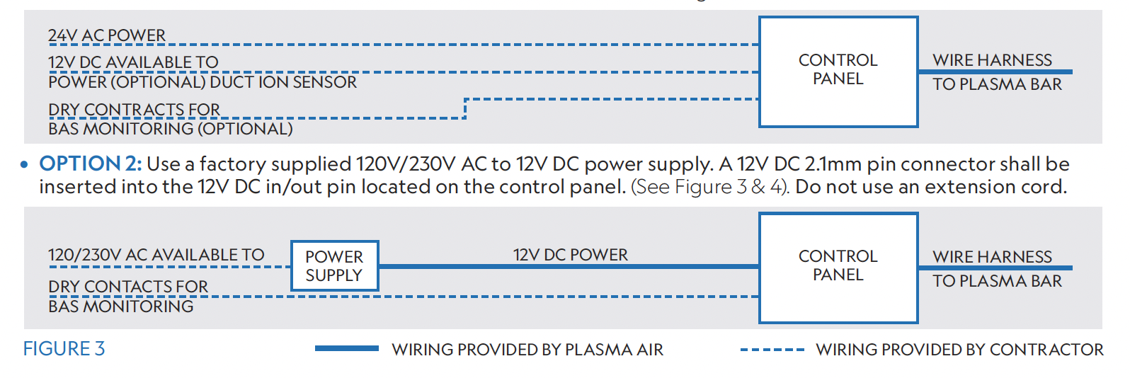
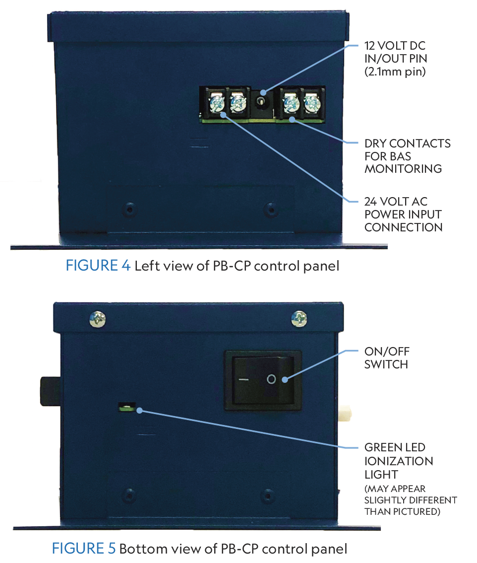
- Power may be connected to the ionization unit using either of the following methods:OPTION 1: Connect 24V AC directly to the power input terminal block on the control panel where indicated. The line and neutral wires can be connected to either screw terminal. (See Figure 3 & 4).
DUAL BAR SYSTEM WIRING INSTRUCTIONS
For applications where two linked BARs are required, follow the wiring instructions listed below. Accessories Required: 3 x Ring Terminals per (2) BAR system.
Remove the white cover plate with the Plasma Air logo from BAR #1 exposing its ring terminals.
- Snip the control panel connector off the end of the wiring from BAR #2 and attach the new ring terminals to the loose wire ends.
- Lay the new ring terminals from BAR #2 on top of the exposed ring terminals on BAR #1.
- Reattach the cover plate on BAR #1. Connect BAR #1 to the Control Panel using the standard factory connector.
DUAL BAR SYSTEM WIRING INSTRUCTIONS
For applications where two linked BARs are required, follow the wiring instructions listed below. Accessories Required: 3 x Ring Terminals per (2) BAR system.
Remove the white cover plate with the Plasma Air logo from BAR #1 exposing its ring terminals.
- Snip the control panel connector off the end of the wiring from BAR #2 and attach the new ring terminals to the loose wire ends.
- Lay the new ring terminals from BAR #2 on top of the exposed ring terminals on BAR #1.
- Reattach the cover plate on BAR #1. Connect BAR #1 to the Control Panel using the standard factory connector.
OPERATION
- When power is supplied to the Plasma BAR Control Panel and the switch is in the "on" position, the Plasma BAR ionization assembly will be activated with the supply fan.
- The Plasma BAR ionization unit is self balancing and does not require any type of adjustment.
- The benefit of the Plasma BAR ionization system is realized only when the supply fan is running. Therefore, to achieve improved air quality, interlock the Plasma BAR Control Panel to be activated with the supply fan.
MONITORING CIRCUIT
The Plasma BAR Control Panel includes a monitoring circuit to verify operation status. The circuit consists of a relay with isolated normally open contacts. The contacts remain open whenever the ionization system is not powered or if there is a fault in the equipment. Whenever the ionizer is energized and producing ions, the normally open contacts close and the green ion indicator light will illuminate. Connect the monitoring control wires of the Building Automation System (BAS) to the dry contacts on the unit. (See Figure 4 & 5).
TROUBLESHOOTING & MAINTENANCE
The Plasma BAR ionizer should be inspected annually to ensure optimal performance. If any dust has built up on the tip of the ionizing needles, this can be removed using a simple cotton swab or compressed air. The control panel requires no maintenance of any kind.
- If the Plasma BAR ionization unit is not working, check that: The control panel power switch is in the "on" position, the supply fan is running and the green ion indicator light is illuminated.
- The power input connections to the control panel are properly connected. Verify all connections are correct and securely tightened. Reconnect any loose wires.
- Test the BAS alarm dry contacts using a multimeter set to continuity mode (Ohms symbol). If the multimeter buzzes the circuit is continuous and operation is normal. If it does not buzz the circuit is broken. Verify other steps and contact support if needed.
- If the control panel internal fuse is blown, wait 2 minutes to allow the unit to automatically reset the fuse. Turn on the power to the control panel. If the fuse blows again, return the control panel to the factory for service.
SEQUENCE OF OPERATION
- For units that are interlocked with the supply fan control, the BAS controls the start/stop of the air conditioning unit supply fan.
- After a one minute time delay on a call for supply fan operation, the BAS monitors the ionization system via the control panel.
- Open contacts indicate a fault; closed contacts indicate normal operation.
Was this article helpful?
That’s Great!
Thank you for your feedback
Sorry! We couldn't be helpful
Thank you for your feedback
Feedback sent
We appreciate your effort and will try to fix the article